
To turn the Raspberry Pi Pico into an Internet of Things (IoT) device, you need to add wireless connectivity. I thought I’d give it go, to see how straightforward it might be to connect the Pico to cellular networks and have a bare-metal app written in C++ run the show. For a modem, I chose to use Waveshare’s suitably sized Pico SIM7080G Cat-M1/NB-IoT.

Cat-M1? NB-IoT? These are 4G-and-beyond connectivity profiles defined by the GSMA, the body that oversees world mobile telephony standards. They’re specifically intended for IoT applications. NB-IoT uses narrowband frequencies: it’s aimed at devices that communicate rarely and only transfer small amounts of data when they do. Cat-M1, aka LTE-M, on the other hand, is broadband. True, it’s not a full 4G or 5G data connection, but then it’s aimed at IoT products not phones: devices that communicate frequently but are not uploading or downloading bulk data.
The key thing about IoT is that it’s not about computers. Take the Raspberry Pi. Sure, some folk use it as the basis for IoT projects, but it’s not a ‘thing’. It’s a powerful, general purpose device being used for a single task. Things — in the IoT sense — are single-application gadgets. They have very different connectivity and security profiles than a personal computer does. You install them and largely forget about them while you focus on the functions they enable or the data they generate. They’re embedded devices, and that’s why the Pico’s RP2040 microcontroller is an ideal foundation for IoT projects and products.

Anyway, back to the Waveshare board. It’s slightly wider and a bit longer than the Pico, which it’s designed to hold piggyback fashion. Waveshare bundles male and female header connectors. I soldered on the female headers, which accept a Pico and have a sufficient pin length to fit solidly into a solderless breadboard too. For a finished design, you could just solder the Pico right onto the Waveshare board. Even the SWD pins are present. The Waveshare is available with a variety of region-oriented modems, but I chose the global model, the 7080G.
There is one downside of the small form-factor: the U.FL antenna connector used here is even tinier than the ones you usually see on modem HATs for Pi products. This one is particularly fiddly to connect. The bundled antenna is large, chunky and heavy enough to pull the connector out on a regular basis. I don’t know how many insertions for which the U.FL connector is rated, but I must have burned through a fair few of them over the past couple of weeks.

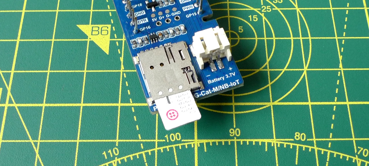
That applies to the GNSS (Global Navigation Satellite System) antenna connector too. Waveshare nicely includes an active GNSS antenna in the box. I’m saving this for later exploration. Likewise powering the setup by rechargeable battery, which the board also supports. A 3.7V LiPo battery is included in the package. You get a lot for your £25-35, depending on where you buy it from.
One other gotcha: the Waveshare board’s GND holes are connected to a large ground plane so they take a bit more time to heat up during soldering than the other holes do. Make sure you keep your iron’s tip in place longer with the GND holes, or the solder will just stick to the pin and not to the board too.
Pico and Waveshare board assembled, and with a nano SIM slotted into the board underneath — make sure it’s a 1.8V SIM; fortunately most are — it’s the software that comes next.
I used a Twilio Super SIM, which provides access to a huge number of networks globally. Full disclosure: I work for Twilio so of course that’s what I’m going to use. However, there are plenty of alternatives out there. Super SIM provides an API-driven mechanism for sending machine-to-machine (M2M) SMS messages to a device and receiving others back. For IoT, that’s a good place to start, but I also coded in HTTP comms to talk to REST APIs.
IoT demo hardware
To try all this out, I built a sample IoT device that has an LED display to communicate with the user, and a sensor to feed data back to base. Both display and sensor, mounted on breakout boards, connect to the Pico over the same I2C bus. These are the parts I used:
- An MCP980 sensor, mounted on an Adafruit board.
- An HT16K33-based four-digit, seven-segment LED display, also from Adafruit.
And here’s the circuit, spread out to make it easy to see:

It’s a very straightforward layout, but then the idea is not to build an IoT device with a specific function which you, as the reader, may not need, but to demonstrate by example how to start building the functionality you do want. In part two, I’ll go over the code, which you can use as the foundation for your own Pico-based IoT device.
Code in C++
The key function the software needs to perform is to communicate with the modem. The Pico C/C++ SDK provides good UART support, so it’s ready to communicate with the SimCom 7080G using AT commands. The Waveshare board uses the RP2040’s UART 0 on GPIO pins 0 (TX) and 1 (RX), plus pin 14 for toggling the modem on and off. It has some quirks too — what modem doesn’t? — so even though the data sheet warns you to wait for two seconds between powering up the 7080G and sending it AT commands, in fact you need to wait closer to 30s for the modem to boot and the UART to become responsive.
Modem communications is textual, so it’s all string manipulation. For that reason, I decided not to use C but C++ which has much friendlier string functions that allows you to leave behind all that tedious mucking about with char arrays, pointers and nul terminators. However, the Pico SDK was created for C usage, so there’s sometimes a little bit of C compatibility your code will need. To pass strings to printf() for debugging output, you also have to feed in C strings. Fortunately, C++’s string library provides the .c_str() method just for these occasions.
An IoT application will use AT commands to configure the modem’s cellular connection — in particular setting its APN (Access Point Name), which identifies how data is routed. Once the modem is attached to the network and authorised to access it — that’s where the SIM comes in — the code can sit and wait for incoming messages. It parses these for commands. When it detects one, it performs the appropriate action. AT commands are used to read the incoming message and to delete it afterward.
Listening for messages is just a matter of periodically sampling the UART and seeing if the modem has signalled the arrival of a message. A more sophisticated approach is to have the arrival of data on the UART trigger an interrupt, rather than polling, but that’s something I’m saving for a future version.
Two-way communications by SMS
SMS messages are limited to a specific character set which doesn’t include the braces that are a key part of the JSON standard. I like to use JSON to format commands to IoT devices and any data they use. To square this circle, I decided to base64-encode the JSON because this format uses characters compatible with the SMS character set.
A key benefit of Super SIM is that all of its features are accessible through an API. In other words, it’s programmable. So sending test messages, for instance, is just a matter of firing off some curl statements at the command line. From there you can build entire applications that can communicate with the API — and therefore your IoT device. The communication is two way: you specify a URL to which Twilio will relay incoming messages — ie. those from the device — and your application extracts the message payload from the incoming GET or POST request.
To use a Super SIM, you’ll need to create a Twilio account, order a SIM and then configure it. Twilio has a great tutorial to walk you through that short process. One point to note: Super SIM doesn’t support NB-IoT, so you’ll certainly need an alternative SIM if you specifically want to try out that connection technology.
That’s the hardware and the broad design — in part two, I’ll cover the code itself.
More on the Raspberry Pi Pico
- How to build a cellular IoT device with the Raspberry Pi Pico — part two, the code
- How to pop up a Picoprobe from the Adafruit QT Py RP2040
- Raspberry Pi Pico proxies: the Pimoroni Tiny 2040 and the Adafruit QT Py RP2040
- Introducing C++ programming on the Raspberry Pi Pico
- Enjoy some old school 3D arcade action — courtesy of the Raspberry Pi Pico
- Play Hunt the Wumpus, Raspberry Pi Pico style
- How to Debug a Raspberry Pi Pico with a Mac, SWD and… another Pico
- How to program the Raspberry Pi Pico in C on a Mac
- A First Look at a MicroPython Marvel: The Raspberry Pi Pico
