
A little while back I wrote about Adafruit’s QT Py RP2040 and how it makes a nice, compact Picoprobe. That’s a Raspberry Pi RP2040-based device used as a bridge between your computer and a target device for debugging work using Single Wire Debug (SWD). I first used the QT Py RP2040’s side-mounted GPIO pins, but SWD hosting is a great role for the device’s QT Stemma connector.

So here’s how you modify the Raspberry Pi Foundation’s Picoprobe source code to get it to work.
I’ll assume you are doing this on a Mac because that’s the purpose of these posts. I’ll also assume you’ve installed Microsoft’s VS Code and you plan to use it for RP2040 development. You’ve probably already installed the Pico C/C++ SDK, but if not, pop over to this post to learn how to install it with the ARM cross-compiler you’ll need too.
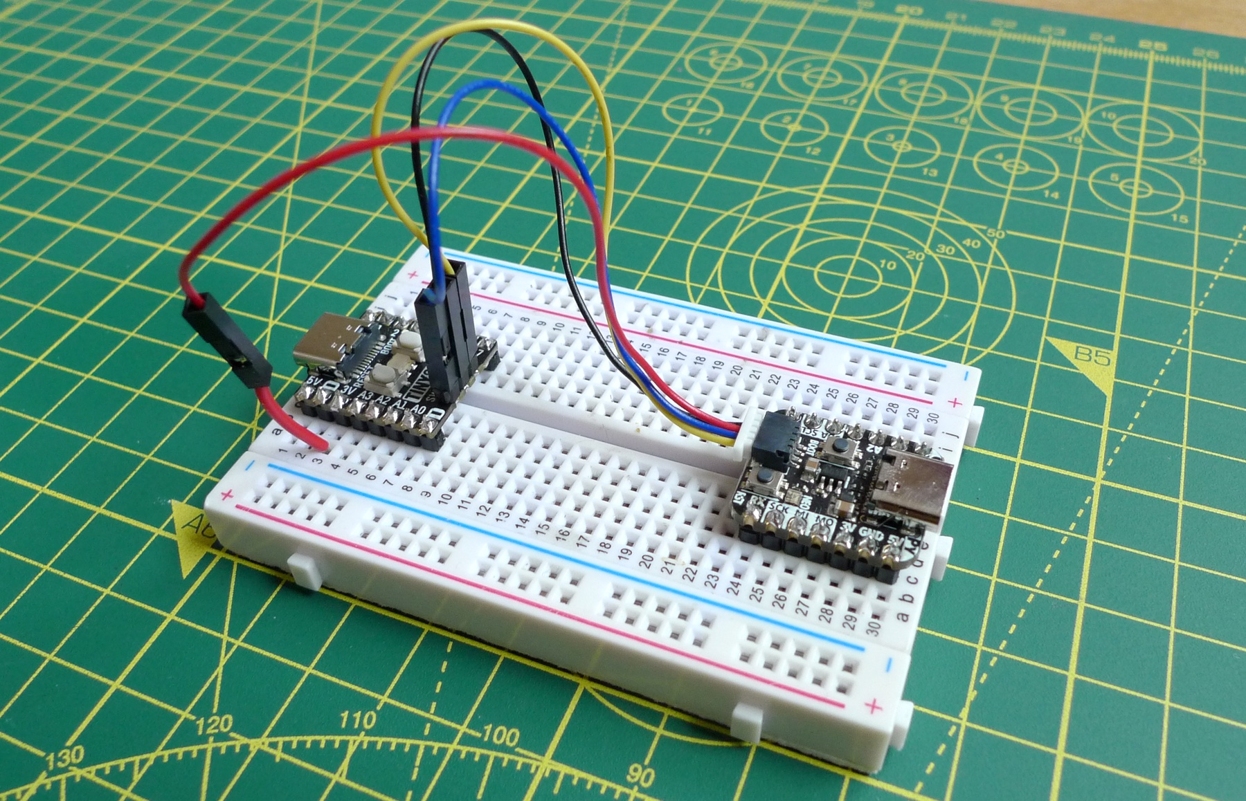
In addition to a QT Py RP2040, you’ll also need a QT Stemma cable. You can pick these up from online retailers and eBay sellers quite cheaply. Mine is has yellow and blue wires for signals, but yours may differ. Mine has female pins, so I soldered a male header to my target device’s SWD breakout. You can orientate yourself from the standard red and black power and ground lines at one end. Yellow will be the SWD data line, blue the clock line.

Now get the Picoprobe source. Open Terminal and cd to your main code directory. Now run these commands:
git clone https://github.com/raspberrypi/picoprobe.git
cd picoprobe
git checkout -b qtpy
In Finder, drag the picoprobe folder to the VS Code icon in the Dock or in the Applications folder. In the Explorer sidebar (hit Cmd-B if it’s not already showing) locate the file /src/picoprobe_config.h and select it.
Look for the section // PIO config and change lines below it to read:
#define PROBE_SM 0
#define PROBE_PIN_OFFSET 22 // Use the QTPy's QT Stemma
#define PROBE_PIN_SWCLK PROBE_PIN_OFFSET + 0 // 22 BLUE
#define PROBE_PIN_SWDIO PROBE_PIN_OFFSET + 1 // 23 YELLOW
PROBE_PIN_OFFSET is used elsewhere in the Picoprobe code, so you don’t set fixed values for the two pins.

picoprobe_config.hClick Build in VS Code’s status bar to build the picoprobe code. It’ll make a build folder and in there you’ll eventually see the file picoprobe.uf2.
Hold down the QT Py RP2040’s BOOT button, connect it to your computer, then release BOOT. Drag picoprobe.uf2 to the mounted RPI-RP2 disk.
Now you can connect a QT Stemma cable to the QT Py RP2040 and run the blue, black and yellow wires to the target device’s SWCLK, SWGND and SWDAT pins, respectively. Connect the red line to the target’s 3V pin.

Use my makepico utility to make a new project. Use the -d flag to configure the project for SWD debugging:
makepico -d ~/test_projectFor the rest, check out this SWD-on-Pico post, but if you’ve already done so, or used SWD on the Pico, you’ll know what to do to run and debug your code via VS Code.
At this point, you might be wondering about the QT Py RP2040’s RGB Neopixel. Can we use that in place of the Pico’s plain old monochrome LED, which flashes is sync with data written out of the Picoprobe? Yes we can. To do so requires adding some extra code to the standard Picoprobe source so that we can drive the Neopixel using the RP2040’s Programmable IO (PIO) facility. Unlike the Pico LED, the Neopixel has two pins, one for power (on GPIO 11), the other for data (GPIO 12).
Rather than cover it line by line, here’s the gist:
- Add the Raspberry Pi Foundation’s WS2812 PIO example code to the project — you need the
ws2812.piofile. - Update the Picoprobe
CMakeLists.txtto generate a C header file forwS2812.pio. - Add
src/ws2812.cto the list of executables inCMakeLists.txt. - Copy the Picoprobe
led.candled.hfiles asws2812.candws2812.h, and change the latter’s function names fromled_xxxtows2812_xxx. - Add the
put_pixel()andurgb_u32()functions from the WS2812 sample code to yourws2812.c. - Update
main.candprobe.cto use the functions inws2812.crather thanled.c. - Build and install.
To make it more flexible, I added an add_definitions() statement to CMakeLists.txt to add the compiler flag USE_WS2812:
add_definitions(-DUSE_WS2812)The -D at the start of the flag name is part of the definition, not part of the name. You can use the flag in #ifndef… #else… #endif structures in main.c and probe.c to branch at compile time to use the standard LED code or the WS2812 code. For example:
#ifndef USE_WS2812
    led_signal_activity(total_bits);
#else
    ws2812_signal_activity(total_bits);
#endif
I used the same approach in picoprobe_config.h to retain the old settings and include the new ones:
#define PROBE_SM 0

#ifndef USE_WS2812
#define PROBE_PIN_OFFSET 2 // Use the Pico LED
#else
#define PROBE_PIN_OFFSET 22 // Use the QTPy's QT STEMMA
#endif

#define PROBE_PIN_SWCLK PROBE_PIN_OFFSET + 0
#define PROBE_PIN_SWDIO PROBE_PIN_OFFSET + 1

#define NEO_SM 1
#define NEO_PIN_PWR 11
#define NEO_PIN_DAT 12
Finally, I tweaked the code to make setting the Neopixel colour a little more easy. The Neopixel takes colours as GRB (Green Red Blue) values, but since most of use think in RGB, I modified put_pixel() to take an RGB value which it then converts to GRB.
I also created a constant, RGB_COLOUR, at the top of ws2812.c so you can set your preferred colour as an RGB value. The file’s functions use the constant when they set the Neopixel’s colour, by passing it into put_pixel().
You don‘t have to key all this lot in yourself — unless you want to — because you can grab it from my picoprobe fork on GitHub, in the qtpy_rp2040 branch.
More on the Raspberry Pi Pico
- How to build a cellular IoT device with the Raspberry Pi Pico — part two, the code
- How to build a cellular IoT device with the Pico — part one, the hardware
- Raspberry Pi Pico proxies: the Pimoroni Tiny 2040 and the Adafruit QT Py RP2040
- Introducing C++ programming on the Raspberry Pi Pico
- Enjoy some old school 3D arcade action — courtesy of the Raspberry Pi Pico
- Play Hunt the Wumpus, Raspberry Pi Pico style
- How to Debug a Raspberry Pi Pico with a Mac, SWD and… another Pico
- How to program the Raspberry Pi Pico in C on a Mac
- A First Look at a MicroPython Marvel: The Raspberry Pi Pico
