
While documenting Twilio’s in-development Microvisor IoT platform, I’ve been working with FreeRTOS, the Amazon-owned open source real-time operating system for embedded systems. Does FreeRTOS work with the Raspberry Pi Pico’s RP2040 chip? I wondered. It turns out that it can, and this is how you set up a very basic FreeRTOS project which also serves as a demo.
There are a small number of blog posts and GitHub- or GitLab-hosted sample projects for the Pico, but they all assume a working knowledge of FreeRTOS. With this post, and in the accompanying GitHub repo, I’ve not made that assumption, so hopefully folk who are new to FreeRTOS will be able to better understand what’s being done and why.
The FreeRTOS Advantage
FreeRTOS provides embedded devices with the kind of multi-tasking you’ll be used to on your computer. Generally an embedded processor won’t be running multiple apps, but its application might benefit from the ability to run multiple app tasks in parallel, just like a single app process on your computer might span multiple threads. The OS switches the processor between all these tasks or threads millions of times a second to make it seem to the user that they’re all working at once.
Why build a Pico app this way? Because the app might benefit from one task running periodically and consistently to update a display and check for user input, while a second task, which processes Internet-sourced data retrieved from a connected modem, like in my Cellular IoT project, only needs processor core resources when it has numbers to crunch.

This ability to schedule multiple threads is doubly handy for the RP2040, which has two cores to play with. Scheduling across the RP2040’s cores has been demonstrated for FreeRTOS and once fully baked in will allow tasks to schedules across both cores automatically.
Building a FreeRTOS App
A FreeRTOS project essentially needs to compile the OS as a library and link it into the the final application binary file. In the case of Pico applications, the binary is the linker-output .elf file that is then used to generate the .uf2 file that you copy across to the mounted board.
FreeRTOS is configured using a standard file, FreeRTOSConfig.h, which sets up the OS to make use of the specific capabilities of the chip on which it’ll be run. This file, plus some application code and Cmake configuration files and the Pico SDK, form the basis for an RP2040 FreeRTOS application, so I’ve put them all together as a project template.
Working with Submodules
Both FreeRTOS and the Pico SDK are included in the template as Git submodules. This means that the remote copy doesn’t include all those projects’ source files, just a reference to them. You still need the code locally to build the application, so once you’ve cloned the template repo and jumped into its directory, you need to run:
git submodule update --init --recursive
to pull down the code. The --init sets up the local repo records; --recursive makes sure you download any submodules that your own submodules reference. Whenever you want to check for and download FreeRTOS and Pico SDK updates, just run git submodule update --init --recursive again.
For a Pico project, adding FreeRTOS is a matter of including the FreeRTOS source code files and FreeRTOSConfig.h in the project’s CMakeLists.txt file, which of course also pulls in and initialises the Pico SDK.
For clarity, I organised my project folder with the app source code in an App folder, FreeRTOSConfig.h in a Config folder, folders for the Pico SDK and FreeRTOS, and the top-level CMakeLists.txt and pico_sdk_import.cmake files:

I also created a subsidiary CMakeLists.txt for the App folder, which is called from the main file:
set(APP_SRC_DIRECTORY "${CMAKE_SOURCE_DIR}/App")

. . .

add_subdirectory(${APP_SRC_DIRECTORY})
In fact, part of my work on setting up this project involved spending some time getting to know Cmake better and taking the opportunity to streamline CMakeLists.txt. As you can see from the snippet above, Cmake supports variables, so I set a lot of project-specific info early and reference it throughout the two files by variable. This makes it a lot easier to duplicate the files for other projects:
# Set project data
set(PROJECT_NAME "FREERTOS_PROJECT")
set(VERSION_NUMBER "1.0.0")
set(BUILD_NUMBER "1")

# Make project data accessible to compiler
add_compile_definitions(APP_NAME="${PROJECT_NAME}")
add_compile_definitions(APP_VERSION="${VERSION_NUMBER}")
add_compile_definitions(BUILD_NUM=${BUILD_NUMBER})
I’ve included the Pico SDK in the template, but you don’t need to do so if you have already installed it elsewhere and have set and exported the environment variable PICO_SDK_PATH. The template’s main CMakeLists.txt file sets PICO_SDK_PATH to the local SDK solely for its run, but you can disable this by commenting out this line:
set(ENV{PICO_SDK_PATH} "${CMAKE_SOURCE_DIR}/pico-sdk")Aside from this, the main CMakeLists.txt sets some project specific variables, imports pico_sdk_import.cmake and initialises the SDK. Next it adds the FreeRTOS source files as static library which will be linked into the application at build time:
# Add FreeRTOS as a library
add_library(FreeRTOS STATIC
    ${FREERTOS_SRC_DIRECTORY}/event_groups.c
    ${FREERTOS_SRC_DIRECTORY}/list.c
    ${FREERTOS_SRC_DIRECTORY}/queue.c
    ${FREERTOS_SRC_DIRECTORY}/stream_buffer.c
    ${FREERTOS_SRC_DIRECTORY}/tasks.c
    ${FREERTOS_SRC_DIRECTORY}/timers.c
    ${FREERTOS_SRC_DIRECTORY}/portable/MemMang/heap_3.c
    ${FREERTOS_SRC_DIRECTORY}/portable/GCC/ARM_CM0/port.c
)
Add key FreeRTOS directories to trigger the loading of the OS’ own CMakeLists.txt files:
# Build FreeRTOS
target_include_directories(FreeRTOS PUBLIC
    ${FREERTOS_CFG_DIRECTORY}/
    ${FREERTOS_SRC_DIRECTORY}/include
    ${FREERTOS_SRC_DIRECTORY}/portable/GCC/ARM_CM0
)
At the end I add the App directory so that its own CmakeLists.txt files is loaded and processed. What’s included in that file? This is where the application’s source code files are compiled and then linked to the compiled SDK and FreeRTOS libraries:
# Include app source code file(s)
add_executable(${PROJECT_NAME}
    main.c
)

# Link to built libraries
target_link_libraries(${PROJECT_NAME} LINK_PUBLIC
    pico_stdlib
    hardware_gpio
    FreeRTOS)
I also include the usual Pico STDIO debugging options, which I’ll access in the app’s code:
# Enable/disable STDIO via USB and UART
pico_enable_stdio_usb(${PROJECT_NAME} 1)
pico_enable_stdio_uart(${PROJECT_NAME} 1)

# Enable extra build products
pico_add_extra_outputs(${PROJECT_NAME})
A Script For Device Installation
I cap all of this off with a shell script, deploy.sh, which takes a path to the built .uf2 file and transfers it to your RP2040-based board. If you include the --build flag, it’ll compile the code for you too.
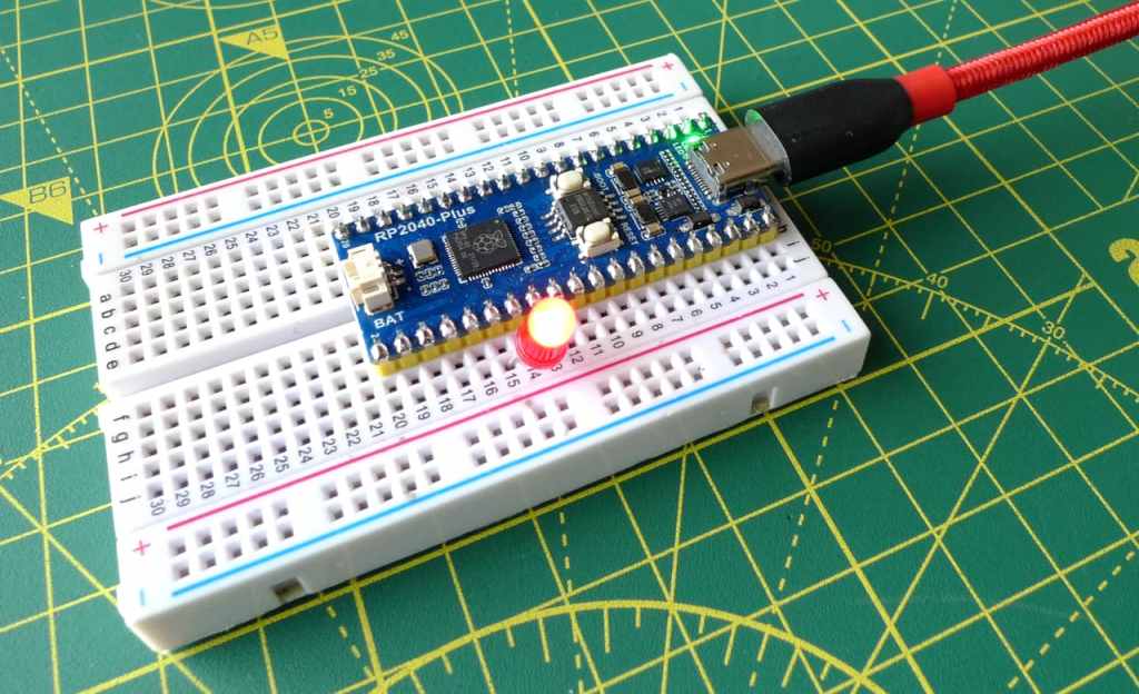
To try the project out, I made use of Waveshare’s RP2040-Plus board, a new RP2040-based development device. Like many of the more recent Pico clones, it includes not only a BOOTSEL button but also a RESET button, and this makes loading fresh application code a lot more straightforward than it is with the Raspberry Pi board. Rather than hold BOOTSEL and then reconnect the USB cable, you hold BOOTSEL, tap RESET and release BOOTSEL. The RP2040-Plus immediately reboots into code-load mode. No faffing with the cable is required.

deploy.sh will wait 30 seconds for you to do this, and copy over the compiled and linked .uf2 file as soon as the standard RPI-RP2 volume mounts on your machine.
The Demo App
Finally, let’s have a quick look at the application itself, in App/main.c.
It flashes two LEDs, one of them the one built into the board, the other connected to GPIO pin 20. Using FreeRTOS for this is massive overkill, natch — you could implement it in a handful of lines otherwise — but it does demonstrate some key FreeRTOS features.
The key lines in main() are:
QueueHandle_t queue = NULL;

. . .

xTaskCreate(led_task_pico,
            "PICO_LED_TASK",
            128, NULL, 1, NULL);
xTaskCreate(led_task_gpio,
            "GPIO_LED_TASK",
            128, NULL, 1, NULL);

queue = xQueueCreate(4, sizeof(uint8_t));

. . .

vTaskStartScheduler();
These lines create two named FreeRTOS tasks — the names are primarily for debugging purposes. Each is assigned a stack of 128 words — ie. 512 bytes for the 32-bit RP2040, more than enough for this app — and a priority of 1, which is the mandatory setting when FreeRTOS is set to provide memory allocation, ie. your FreeRTOSConfig.h contains the line:
define configSUPPORT_DYNAMIC_ALLOCATION 1Next the code creates a queue which will be used to pass messages (data) between the two tasks. This one is four entries deep; each entry is one byte in size.
Finally, the code calls vTaskStartScheduler() to tell FreeRTOS to begin running the specified tasks, which are implemented as functions — pointers to each are passed into the calls to xTaskCreate().
The first task function, led_task_pico(), configures the internal LED’s GPIO pin and turns it on an off. Each time the LED’s state is changed, the code also pops that state onto the FreeRTOS queue using xQueueSendToBack(). You don’t add the value directly, but provide a reference to the variable in which it is stored.
vTaskDelay() is how you pause the task for a set period in internal ticks, which we’ve already calculated in terms of milliseconds:
const TickType_t ms_delay = 500 / portTICK_PERIOD_MS;
The second task function, led_task_pico(), configures an LED on GPIO pin 20 and then does nothing but call xQueueReceive() to see if there’s a new message on the FreeRTOS queue. If there is, it copies that value to the memory you specify as a pointer. This is a byte indicating the state of the board’s LED, so we just set this function’s LED to the inverse of that.
void led_task_gpio(void* unused_arg) {
  // This variable will take a copy of the value
  // added to the FreeRTOS xQueue
  uint8_t passed_value_buffer = 0;

  // Configure the GPIO LED
  gpio_init(RED_LED_PIN);
  gpio_set_dir(RED_LED_PIN, GPIO_OUT);

  while (true) {
    // Check for an item in the FreeRTOS xQueue
    if (xQueueReceive(queue, &passed_value_buffer, portMAX_DELAY) == pdPASS) {
      // Received a value so flash the GPIO LED accordingly
      // (NOT the sent value)
      if (passed_value_buffer) log_debug("GPIO LED FLASH");
        gpio_put(RED_LED_PIN, passed_value_buffer == 1 ? 0 : 1);
      }
    }
  }
}
And here’s the result:

There’ll be more on FreeRTOS on the RP2040 in a future post. In the meantime, you can get the template and demo code from my GitHub repo to try it out.
More FreeRTOS
- Fun with FreeRTOS and the Pi Pico: timers
- Fun with FreeRTOS and the Pi Pico: interrupts, semaphores and notifications
- Further Fun with FreeRTOS Scheduling
More Raspberry Pi Pico
- Pico USB serial communications with CircuitPython
- Build a Raspberry Pi Pico WiFi IoT Device
- First look: Pimoroni’s PicoSystem hackable handheld games console
- How to build a cellular IoT device with the Raspberry Pi Pico — part two, the code
- How to build a cellular IoT device with the Raspberry Pi Pico — part one, the hardware
- Raspberry Pi Pico proxies: the Pimoroni Tiny 2040 and the Adafruit QT Py RP2040
- Introducing C++ programming on the Raspberry Pi Pico
- Enjoy some old school 3D arcade action — courtesy of the Raspberry Pi Pico
- Play Hunt the Wumpus, Raspberry Pi Pico style
- How to Debug a Raspberry Pi Pico with a Mac, SWD and… another Pico
- How to program the Raspberry Pi Pico in C on a Mac
