
This post was originally going to be about building a tool to access I²C devices on a Mac, reaching them via USB and an Excamera Labs I2CMini adaptor board. But then I accidentally snapped the pins and board traces off my I2CMini, so I had to go back to the drawing board. Now it’s about accessing I²C devices on a Mac using a Raspberry Pi Pico, or any other RP2040-based board, as the adaptor.
How does that work? The Pico runs custom firmware that handles communications with the host Mac and acts as a bridge between client software on the Mac and the device(s) connected to one of the its I²C buses.
The communications side is an evolution of the mechanism I’ve written about before: how the Pico SDK allows you to route standard input and output over USB. The Mac client writes data to the serial port that the USB-connected Pico presents itself as. The Pic reads this through SDK calls, and can send back data over the same path. I use it in my Motorola 6809 simulator to transfer over ROM data. Here I send commands and data to the firmware.
Like the earlier project, the Pico firmware is again written in C. So this time is the client code.
The firmware sits and listens for incoming commands and data. Commands are single-byte Ascii codes that trigger actions. Data blocks are chunks of up to 65 bytes: a single-byte header which indicates the number of bytes to process and whether they’ll be read or written, followed by up to 64 bytes of data to be sent to a connected USB device.

The coding of commands is clever. I can say that because I didn’t come up with it: James Bowman, who wrote the I2CMini firmware (in Forth) did. Commands are Ascii codes — s to start a bus transaction, w for write to I²C, r for read, x for bus reset, that kind of thing — so their values are all less than 128. That leaves the values from 128 to 255 for the data header: it’s a value that is a base value indicating the operation type (read or write) added to the number of bytes to process minus one. The read operation base is 128 (0x80); the write base value 192 (0xC0).
So if the firmware receives a starter byte of 205 (0xCD), it knows there are 14 bytes of write data to follow. If it receives 159 (0x9F), then that’s a call to read back 32 bytes from the I²C device.
The commands themselves tell the firmware to initialize the I²C bus, to scan for devices and report back what it finds, to send back status information, and to prepare for a read or write transaction. The latter is followed by a byte that contains the target 7-bit I²C address plus a bit to indicate operation type. The next byte that follows will, of course, by a read/write header as described above.
Here are the cli2c commands:
| Command | Args | Description |
|---|---|---|
z |
Initialise the target I2C bus. The bus is not initialised at startup | |
w |
{address} {data_bytes} |
Write the supplied data to the I2C device at address. data_bytes are comma-separated 8-bit hex values, eg. 0x4A,0x5C,0xFF |
r |
{address} {count} |
Read count bytes from the I2C device at address and issue an I2C STOP |
p |
Issue an I2C STOP. Usually used after one or more writes | |
f |
{frequency} | The I2C bus frequency in multiples of 100kHz. Supported values: 1 and 4 |
x |
Reset the I2C bus | |
s |
Display devices on the I2C bus. This will initialise the bus if it is not already initialised | |
i |
Display I2C host device information | |
h |
Display help information |
Args in braces ({ }) are mandatory; those in square brackets ([ ]) are optional.
The firmware currently only allows you to connect devices to the default I²C bus and default pin numbers, but I have an eye on a future update that’ll allow the client to choose these, depending on what is supported by the board itself. For instance, the Pico exposes a stack of SDA and SCL pins for the two I²C buses, i2c0 and i2c1, but the number of available pins is much more limited on RP2040-based boards from Pimoroni, Adafruit and SparkFun.
Building the firmware generates three versions, for the Pico, the SparkFun ProMicro RP2040, the Adafruit QTPy 2040 and the Pimoroni Tiny 2040. Build the code with the usual
cmake -S . -B build
cmake --build build
If the ‘heartbeat’ LED flash bothers you, you can turn it off by commenting out the add_compile_definitions(SHOW_HEARTBEAT=1) line in the top-level CMakeLists.txt file.
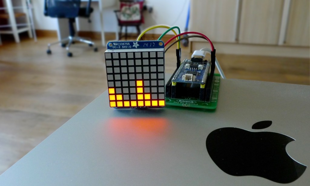
There are three client command-line apps in the inevitable GitHub repo. The first, cli2c, is a generic tool for issuing commands to any I²C connected device; the others, matrix and segment, are application-specific utilities for driving HT16K33-based matrix and segment LEDs, respectively. These two have their own, display-centric commands, and come with some examples to demonstrate their usage.
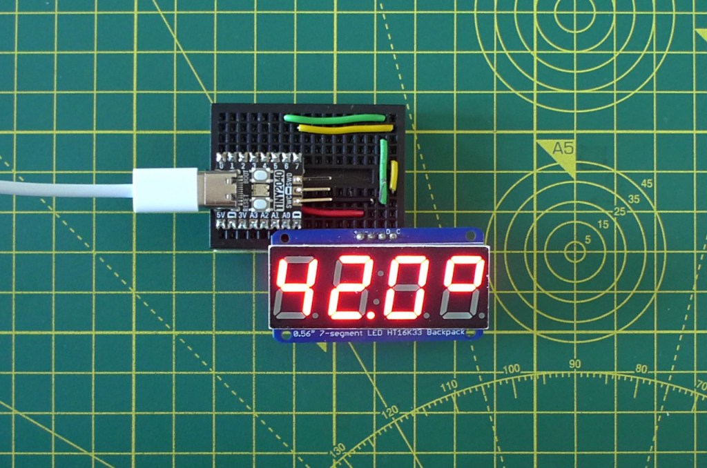
Here’s an example. This line gets the temperature from an MCP9808 sensor.
cli2c /dev/cu.usbmodem101 w 0x18 0x05 r 0x18 2
The first argument is the I²C host’s Unix device file on the Mac. Next we have the w(rite) command followed by the target I²C device’s address (0x18) and then the value we want to send: the address of the register we want to read, in this case the ambient temperature. Then we r(read) from the same device two bytes: the returned 16-bit raw temperature value.
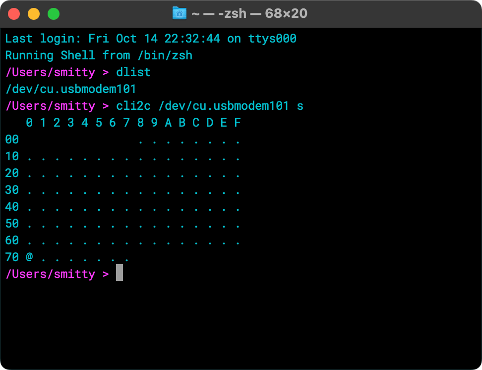
You can get a scan of connected I²C devices like this — ‘s’ for ‘scan’:
cli2c /dev/cu.usbmodem101 s
which yields output like:
The other apps, segment and matrix, provide different commands that are geared toward display. For example, c sets a specified alphanumeric character on the matrix or on a specified digit of the segment; g sets a user-defined character on the matrix or on a specified digit of a segment display. Use r to rotate the matrix buffer by multiples of 90 degrees, or f to flip the segment display through 180 degrees. All the commands are described in the repo’s read me file.
As an example, this command draws a smiley on a matrix display:
matrix /dev/cu.usbmodem101 g 0x3C,0x42,0xA9,0x85,0x85,0xA9,0x42,0x3C
While this command writes 42.4° on the segment display:
segment /dev/cu.usbmodem101 n 4242 d 1 c '*' 3
Decoding the commands: n writes 4242 across the display; d lights the decimal point after digit 1; and c draws the degrees symbol in digit 3. I use an asterisk as a proxy for the degrees symbol, but as it’s a shell function to, it needs to be included here in single quotes.
Here are the matrix commands:
| Command | Args | Description |
|---|---|---|
a |
[on|off] |
Activate or deactivate the display. Once activated, the matrix will remain so for as long as it is powered. Pass on (or 1) to activate, off (or 0) to deactivate. Calling without an argument is a de facto activation |
b |
{0-15} | Set the brightness to a value between 0 (low but not off) and 15 (high) |
c |
{ascii_code} [true|false] |
Plot the specified character, by code, on the display. If the second argument is included and is true (or 1), the character will be centred on the display |
g |
{hex_values} | Plot a user-generated glyph on the display. The glyph is supplied as eight comma-separated 8-bit hex values, eg. 0x3C,0x42,0xA9,0x85,0x85,0xA9,0x42,0x3C |
p |
{x} {y} [1|0] | Plot a point as the coordinates {x,y}. If the third argument is 1 (or missing), the pixel will be set; if it is 0, the pixel will be cleared |
t |
{string} [delay] | Scroll the specified string. The second argument is an optional delay be between column shifts in milliseconds. Default: 250ms |
w |
None | Clear the screen |
r |
{angle} | Rotate the display by the specified multiple of 90 degrees |
And for segment:
| Command | Args | Description |
|---|---|---|
a |
[on|off] |
Activate or deactivate the display. Once activated, the matrix will remain so for as long as it is powered. Pass on (or 1) to activate, off (or 0) to deactivate. Calling without an argument is a de facto activation |
b |
{0-15} | Set the brightness to a value between 0 (low but not off) and 15 (high) |
f |
None | Flip the display vertically. Handy if your LED is mounted upside down |
g |
{definition} {digit} [true|false] | Write a user-generated glyph on the display at the specified digit. The glyph is supplied as an 8-bit value comprising bits set for the segments to be lit. Optionally specify if its decimal point should be lit |
v |
{value} {digit} [true|false] | Write a single-digit number (0-9, 0x0-0xF) on the display at the specified digit. Optionally specify if its decimal point should be lit |
c |
{char} {digit} [true|false] | Write the character on the display at the specified digit. Only the following characters can be used: 0-9, a-f, -, space (use ' ') and the degree symbol (used '*') Optionally specify if its decimal point should be lit |
n |
{number} | Write a number between -999 and 9999 across the display |
k |
None | Light the segment’s central colon symbol |
w |
None | Clear the screen |
z |
None | Write the buffer to the screen immediately |
Args in braces ({ }) are mandatory; those in square brackets ([ ]) are optional.
All three client apps use low-level macOS APIs to talk to the serial port that is the RP2040-based board. In fact, given that the code largely used standard POSIX calls, it’s 95 per cent ready to be recompiled for Linux too. This I may do for a subsequent release: it would be nice to see the code running on a full-blooded Raspberry Pi too.
