
This is a little project I’ve been working off and on now for some time. It’s one of those efforts where you do a heap of work and then leave it alone for months on end while you go off and do something else entirely. Eventually you come back and do a little more, and then something else distracts you. But you know you’ll complete it in the end, and the journey is as much fun as reaching the destination.
My project is building a Motorola 6809e CPU in software. Yes, there are tons of these out there, but this is something I wanted to do for myself. I love the 6809e — it’s the first chip I learned to program using machine code. The project started out some years ago as a Mac app, but in 2021 was injected with a new lease of life as a Raspberry Pi Pico implementation, which is why I’m writing about it now.
The code has two parts. There’s the 6809e simulator, not yet clock precise, but that’s coming. And there’s a monitor program for code entry and debugging. The simulator currently provides an emulated CPU, a bank of 64KB of RAM and in due course Motorola support chips like the MC6821 Peripheral Interface Adaptor (PIA). I plan to add key interrupt lines, relayed via RP2040 GPIO pins, too.
The Monitor Board
The overall start-up sequence checks for the presence of a ‘monitor board’ and if it’s connected, boots the monitor, which runs natively on the Pico so you don’t lose any of the 64KB memory to it. If you boot without a board, the CPU runs its test suite, but that’ll be changed to a proper 6809e start-up sequence shortly.
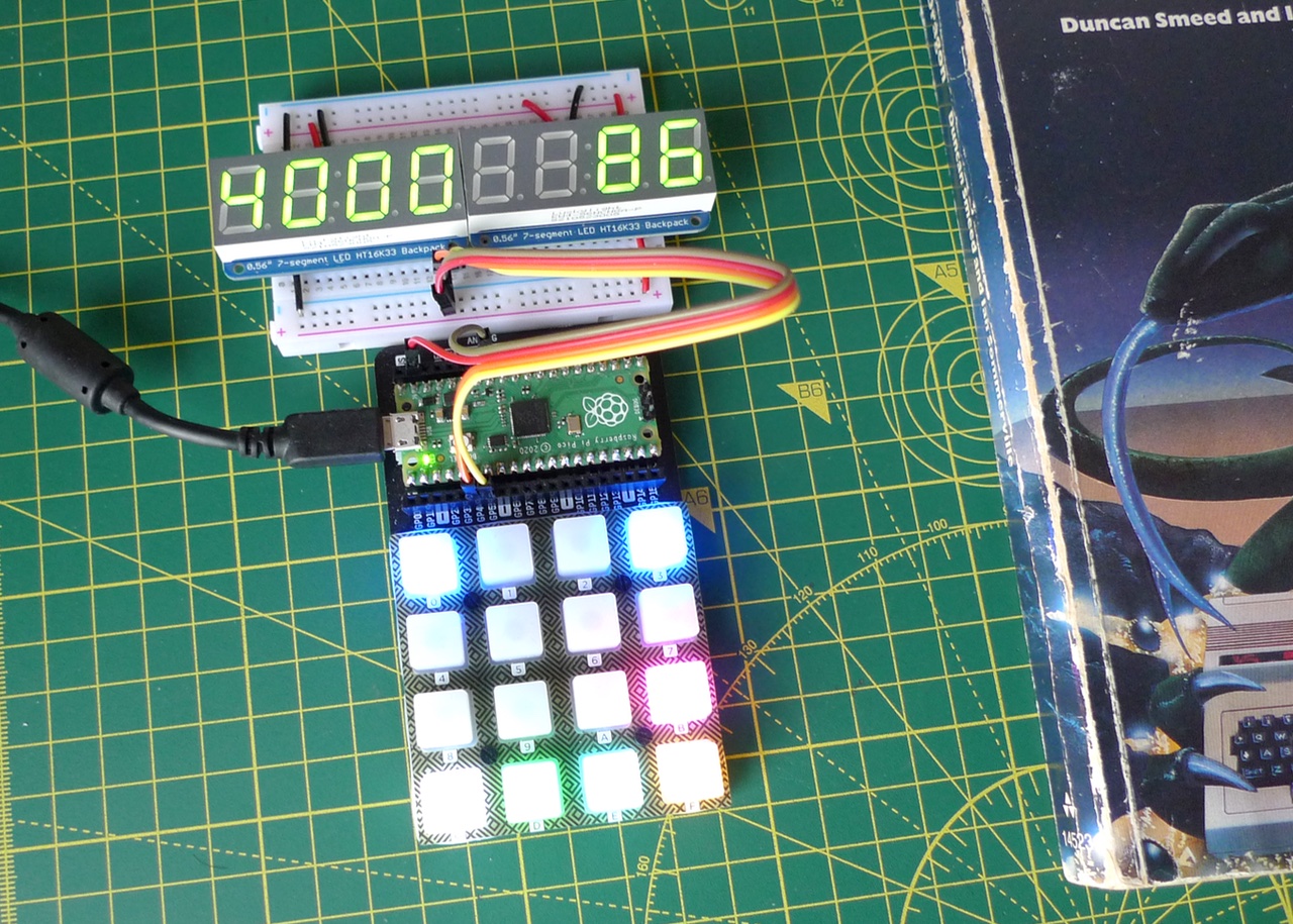
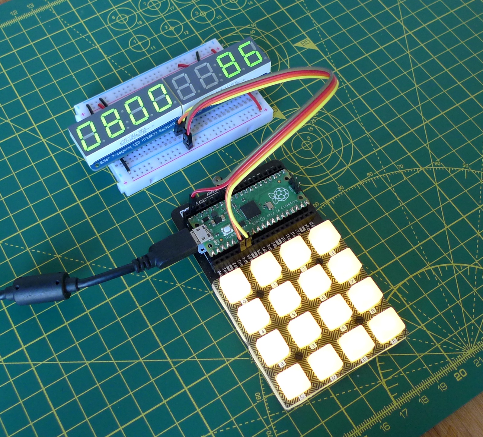
The monitor board is more fun. It’s based on a Pimoroni RGB Keypad, which is a rubbery hexadecimal keyboard that has an APA101 RGB LED underneath each key. A hex pad is just what you need for 8-bit and 16-bit value entry, and the LEDs mean I’ve been able to create a context-sensitive colour-coded UI.

For example, the main menu has a couple of dark blue buttons, one on the left, the other on the right, to step through memory. Yellow and cyan keys let you enter, respectively, a 16-bit address and an 8-bit value. So set an address, then punch in machine code and data byte by byte. With each entry, you can confirm (green key) or reject (red key) the value you just keyed in. Either returns you to the main menu. Apologies to red-green colour-blind folk, of course. When entering bytes, there’s also an orange key which, when pressed, stores the value at the current memory location and gets the board ready receive another byte which will be stored in the next memory location, and so on.
Back at the main menu, you can either run the code at full tilt, or single step through your program instruction by instruction. Real old school.
The keypad has female headers for the Pico, which connects to the LEDs and a shift register for the keys via I²C and SPI. The good thing is that all the Pico’s GPIO are broken out too, so I just soldered on some extra female header and that allowed me to hook up a breadboard with a pair of four-digit, seven-segment LEDs. By default this display shows an address on one side (four hex digits) and the value stored at that address (also in hex) on the other.
When single-stepping through a program, you can tap a magenta key to switch the display to the 6809e’s condition code register (presented as an 8-bit binary value) or groups of registers (A, B and Direct Page; X and Y; S and U). Tap the green key to run the next instruction, or hit red to go back to the main menu. You can also step through RAM on the display; hitting the orange button will resync the displayed address and byte with the current value in the Program Counter.
The monitor code reads the keypad’s TCA9555 shift register via I²C. You read two bytes: the low and then high bytes of a 16-bit bit value. A given bit is clear if the key it represents is pressed. For convenience, I negate the full value. So if you want to know whether, say, the F key is pressed, you test bit 15. My code parses the 16-bit value to return the bit number of the first key pressed. This happens on a key release after press and release debounce periods. I also match against a mask which hides invalid keys for a given UI screen.
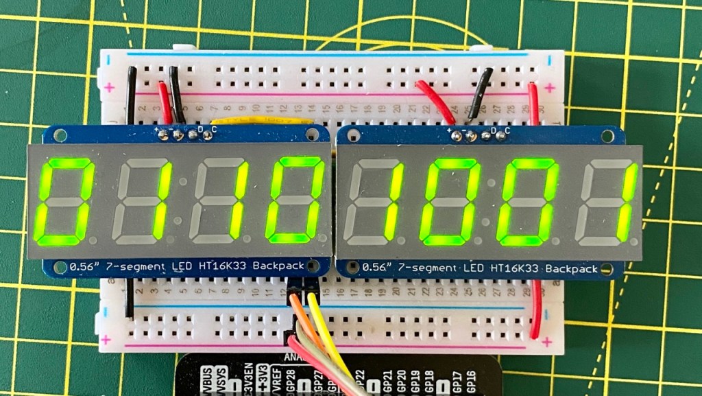
Checking for the presence of the TCA9555 on the I²C bus provides a handy way to see if the monitor board is connected. The two segment LED blocks are hooked up on the same I²C bus — on the Pico’s GPIO pins 4 and 5. GPIO pin 3 is used as a interrupt.
The keypad’s colours are set using SPI: write out a block of data — four bytes per colour (alpha, blue, green, red) per key — so there are routines to write a given key’s colour values into a buffer and to set all the keys to one colour. After setting the colours, I just write the buffer contents out.

The keypad uses Pico GPIO 17 for Chip Select, and pins 18 and 19 for SPI itself (clock and TX, respectively). That plus the I²C pins leaves GPIO 20-22 for the 6809’s interrupt pins, and 6—9 and 10-13 for its PIA chip mediated IO.
The VELA Connection
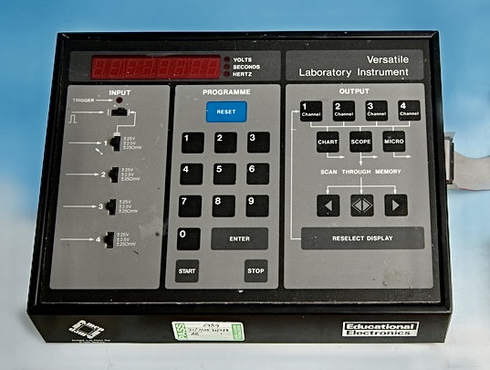
You might wonder why I’ve picked such a masochistic way to enter program code. There are a couple of reasons. First, I thought it would be an interesting approach to try, and then there was the challenge of designing a suitable UI. The other reason is that when I was a student at the University of Leeds’ Physics Department, I got to play with its Vela unit. This had been designed as a digital data capture and manipulation tool for education and lab work. I liked it because it was based on the 6802. It used a membrane keyboard and segment display, so my project is, in part, be my homage to the Vela — short for VErsatile LAboratory instrument — which has long since departed to the great lab in the sky.
Indeed, one of the things I’m going to include with the virtual CPU is a Motorola PIA chip that’ll read or write to eight lines and interrupt the CPU when required. This is why I chose to re-implement all this on a Pico: lots of GPIO.
Now I’m not entirely given over to writing machine code and punching it into memory byte by byte, so the monitor also supports feeding in code via USB from binary files on a host Mac. This uses the approach outlined in an earlier post: send files via stdio. I plan to add in due course saving files to the computer.
Back when I started developing the virtual 6809, I wrote a 6809 assembler in Python. It was tailored for the Mac version, but I’ve since dusted it down and allowed it to write out binary (.rom) files too. The byte transfer system reads in such .rom files and sends the data to the monitor board via USB.
As I said at the start, I’m doing this entirely for myself. However, because all the hardware is based on off-the-shelf parts — it’s really easy to assemble yourself. Head over to my e6809 repo for the code and further instructions. I’ll be working on the pico branch.
