
Last time, I covered the basics of doing ARM assembly programming on the Raspberry Pi Pico’s RP2040 microcontroller. Now it’s time to get to grips with the dozens of instructions to which the RP2040’s Cortex-M0+ cores respond.
Each instruction is just a number, encoded to indicate the operation itself, what registers it uses, and any other relevant data. But because encoding numerical instructions is hard, assembly programming instead represents instructions in a textual shorthand. Because these codes are easier to memorise than are the numbers they represent, they’re called ‘mnemonics’ — pronounced ‘nemonix’. The assembler converts the mnemonic ‘operator’ plus a value derived from its various ‘operands‘ into a numeric value — and that’s the machine code that the MCU executes.
op operand_1, operand_2, operand_3
Operators, or ‘ops’, can be grouped by type. The ones you’ll use most frequently involve loading numbers into register from memory, moving numbers into registers from other registers or as specified values, performing arithmetic on registers’ contents, and writing the results back to memory again. These are the groups of ops I’ll cover here — in future installments, I’ll go over branch ops, logical ops and the rest.
Let’s look at the instructions you’ll use to get data into registers. You can get the full details from ARM’s documentation, such as this handy reference card, so I’ve focused on the key points.
Loads and Stores
Load Register — LDR
This fills one register with one or more bytes from memory. The address of that memory is stored in another register — it’s used as a pointer. This is called “indirect addressing”, and it’s indicated by placing square brackets around the pointer register and any optional offset to its value. The basic form is:
LDR<type> Rd, [Rn, #<offset>]
This means load the destination register, Rd, with the value stored at the x bytes whose first address is the value stored in Rn plus offset. If offset is zero, you can omit it:
LDR<type> Rd, [Rn]
If Rd and Rn are different, offset is a 5-bit value; if they are the same, it’s an 8-bit value. To complicate matters, the offset actually applied is four times that value, because word addresses have to be four-byte aligned, ie. divisible by four. The maximum 5-bit value is 31, which gives us an actual offset range of 0-124 (4 x 31). The actual 8-bit range is 0-1020 (4 x 255). The assembler assumes you’re giving an actual value, not one in the base range.
The offset can also be a value held in another register, which is handy if you need a calculated offset or an offset larger than an immediate offset will give you:
LDR<type> Rd, [Rn, Rm]
Let’s talk about <type>. It’s a character indicating the loaded value’s type. Omit it if you’re loading an unsigned 32-bit value, but add H for an unsigned 16-bit value (Halfword), or B for an unsigned 8-bit value (Byte). If the number is signed, prefix <type> with S; use SW for a signed 32-bit number.
LDRB R0, [R1] @Load just a byte
You can use SP and PC in place of R13 and R15 to make working with those registers more explicit — this works for most ops. You can also use labels:
LDR R0, data_address
This is considered a special case which will be converted by the assembler into a PC-relative instruction:
LDR R0, [PC, #offset_to_data_address] @PC-relative addressing
Load Multiple — LDM
With a single op, LDM, you can fill two or more low registers (R0-7) with the contents of the memory pointed to by another register:
LDM Rn<!>, {comma separated list of low registers}
Include the ! to increment Rn with the number of bytes loaded, handy for loop counters. For example, if three registers are specified in the list, that’s 12 bytes (3 x 4 bytes), so Rn += 12. If Rn is included in the list of low registersd, it won’t be updated with the increment, even if you’ve added the !.
The registers will be loaded in number order, not in the order you list them.
Store Register — STR
Store ops write the contents of a register to memory by specifying the first byte of memory. Like loads, stores primarily use indirect addressing. They use the same <type> definitions and immediate offset rules. The basic form is:
STR<type> Rd, [Rn, #<offset>]
Again, if offset is zero, just omit it:
STR<type> Rd, [Rn]
Or it can be a value held in another register:
STR<type> Rd, [Rn, Rm]
Store Multiple — STM
You can store two or more low registers into the memory pointed to by another register:
STM Rn!, {comma separated list of low registers}
Rn is incremented by the number of bytes written as per LDM. Only low registers can be written out this way. The registers will be written out in number order, not in the order you list them. ARM says Rn should not be included in the list.
Move — MOV/MOVS
You can set a register with a specific value: an 8-bit unsigned integer or the contents of another register. This is called a ‘move’.
MOV Rd, #value                  @Rd = value - immediate addressing
MOV Rd, Rn                      @Rd = Rn - register addressing
These ops work with any register, but they don’t affect the PSR. To cause the move to update the PSR — specifically its N(egative) and Z(ero) bits — use the MOVS form, but this only works with the low registers. I’ll cover the PSR in greater detail when I come to branch ops in a subsequent post.
If you use immediate addressing, the destination register’s bits 31:8 or 31:5 are cleared. Moving an address into the PC register is an implicit jump operation.
Arithmetic Ops
Add — ADD/ADDS
What it says on the tin: add register values together.
ADDS Rd, Rn, #<value> @ Rd = Rn + value
If Rd is not the same as Rn, value is a 3-bit number; if they are the same, value can be an 8-bit number and we can drop the first Rd:
ADDS Rd, #<value>
We can add three registers with this form:
ADDS Rd, Rn, Rm @ Rd = Rn + Rm
Again, if Rn or Rm is Rd, we can drop it:
ADDS Rd, Rn @ Rd += Rn
In these case, the registers must all be low — the PSR is also set, hence the S — but you can do the same thing with any register: just drop the S from the op:
ADD Rd, Rn, Rm                   @ Rd = Rn + Rm
ADD Rd, Rn                       @ Rd += Rn
As with the load and store ops, we can use PC instead of R15:
ADD PC, PC, Rm @ PC += Rm
Remember, setting the PC is an implicit jump operation. We can work with the Stack Pointer too:
ADD SP, SP, #<value> @ SP += value
Here value is a 7-bit integer. We don’t have to change SP — we can instead put the result in another register:
ADD Rd, SP, #<value>
Because the SP must contain a value that lies on a word boundary — ie. an address divisible by four — value is multiplied by four, just like the offsets applied in loads.
A special version of this uses a new mnemonic for ‘Address to Register’. It has a label as an operand:
ADR Rd, <label> @ Rd = PC + address of label
This is implemented with PC-relative indirect addressing:
ADD Rd, [PC, #<assembler-calculated offset>]
As such, the label needs to be in the range PC to PC+1020. As with load offsets, the encoded offset gets multiplied by four to generate the maximum word-aligned value.
Finally, a third add op is ‘Add with Carry’:
ADC Rd, Rm @ Rd += (Rm + PSR-C)
This addition includes any carry left over from the previous operation. This is recorded in the PSR register’s C(arry) bit. Again, I’ll cover the PSR in detail in a later post. The carry is set when two 32-bit unsigned integers are added and the result is greater than the highest value that can be expressed with only 32 bits. You use this feature when, say, adding two 64-bit values together. You add the numbers’ least significant 32 bits together and take into account any overflow by adding the numbers’ most significant 32 bits with the carry.
Subtract — SUB
Subtraction ops parallel the addition ops. However, all but one of them work with the low registers — ie. use the S form — and that only works with the SP register. Generally:
SUBS Rd, Rn, Rm @ Rd = Rn - Rm
There are versions with 3- and 8-bit immediate values too:
SUBS Rd, Rn, #<value>            @ Rd = Rn - 3-bit value
SUBS Rd, #<value>                @ Rd -= 8-bit value
The special case usage for the SP register is:
SUB SP, #<value>
Here value is a 7-bit unsigned integer.
There’s also a version that uses any carry from a previous calculation:
SBCS Rd, Rd, Rm @ Rd = Rn - Rm - PSR-C
Reverse Subtraction — RSBS
You can perform a 2’s complement on a low register’s value with this op:
RSBS Rd, Rn, #0 @ Rd = 0 - Rn
Only #0 is permitted for the final operand.
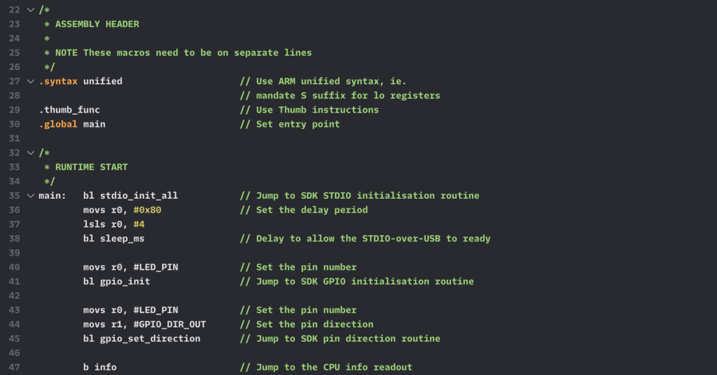
Now, I wanted to test this instruction, but on assembly I received Error: cannot honor width suffix -- rsbs r0,r3,#0. Changing RSBS to RSB had no effect. The solution: add the .syntax unified directive at the start of the .S file. This mandates the correct use of the S suffix on appropriate ops: you must use the S form of ops when you’re working with low registers. Doing a clean build afterwards is recommended. I’ve updated the accompanying GitHub repo accordingly.
Multiply — MUL
Time was you ran a loop of ADD ops to perform a multiplication. Now you call:
MULS Rd, Rm @ Rd *= Rm
Note In ARM documentation, this op is usually listed as MULS Rd, Rm, Rd. However, the Thumb instruction format includes only two registers, not three. Why the redundant final Rd? Who knows — a hangover from the ARMv6 instruction perhaps? Whatever, I use the two-register form I’ve shown above.
Next time: branch ops and the Program Status Register…
