
A number of the Cortex-M0+ Thumb ops I covered last time update the core’s Program Status Register (PSR) based on the outcome of the operation. The ops that do so have an S appended to their mnemonics and they only work with the core’s ‘low’ registers, R0-7.

What does a PSR update mean? It’s time to look at this register more closely. We’re interested in the register’s top four bits (31:28). These are used to record the effect, if any, of the most recent operation that updates the PSR. Those four bits are, respectively, nicknamed N, Z, C and V, for ‘negative’, ‘zero’, ‘carry’ and ‘overflow’. I’ll refer to them as PSR-N, PSR-Z, etc.
The ops we’ve seen that affect the PSR include ADDS and SUBS. If I add two unsigned integers and the result is greater than 32 bits are able to define, that’s a carry, and PSR-C is set. Ditto if the subtraction of two numbers requires a borrow. If I add two positive signed integers and the result is negative (bit 31 is set), or I add two negative numbers and get a positive, that’s an overflow, and PSR-V is set. PSR-N is set to match bit 31 of the result: it indicates if the result is a negative signed integer. This is the case even if you don’t care whether the value is signed or not. If I add or subtract two integers, or manipulate one integer, and the result is zero, PSR-Z is set.
The RP2040’s maths unit doesn’t know about signed and unsigned integers. It just does the sum in binary and sets the PSR flags appropriately. It’s your job to know which flag to check after the sum is done. If you’re doing unsigned maths, you can ignore PSR-V. If you’re working with signed numbers, you can ignore PSR-C.
Comparison Ops
Whenever an S form op is executed, the PSR is updated. Comparison operators are a case in point. These compare the values of two registers, or a register and an 8-bit immediate value, signified by a #.
CMPS r0, r1			@ Update PSR on r0-r1
CMPS r0, #0xAB		        @ Update PSR on r0-0xAB
A comparison is a subtraction but one in which the result is discarded. If R0 minus 0xAB equals zero, the two values are the same. The zero result causes PSR-Z to be set. So we can use CMP and the PSR to perform conditional logic: we can branch to one part of a program or another according to the outcome.
This is how most RP2040 branch ops work. They check a bit in the PSR and jump (or not) according to its state. In the example above, we might want to branch to the label do_something if the two values are the same:
BEQ do_something @ Jump if r0 == 0xAB
That op comprises B for branch and EQ for equal, natch. The equivalent op for inequality is BNE — ‘Branch Not Equal’.
Branch Ops
The beauty of setting the PSR automatically is that you can follow any op that does so with a branch operation — you don’t need to test the value first. Here’s an example, assuming R4 and R5 are set somewhere earlier:
                SUBS r4, r5                 @ R4 -= R5
                BEQ fix_bad_val		    @ Trap cases when they're the same
                LDR r0, =GOOD_VALUE
                B debug_print
fix_bad_val:    LDR r0, =BAD_VALUE
		MOVS r4, #0xFF              @ Re-apply the default
debug_print:    BL printf
		B some_code_to_process_r4
.align 2
GOOD_VALUE      .asciz    "R4 != R5\n"
BAD_VALUE       .asciz    "R4 == R5\n"
There are 14 condition-specifying suffixes you can apply to B to indicate what PSR bit is used to check whether the code needs to branch or not. You can find them at the end of the ARM Thumb Reference Card.
B on its own is a valid op too: it’s an unconditional branch, and you use it, as in the example above, by specifying a label to jump to. The assembler converts this to PC-relative address. If the jump is more than 2KB beyond B, you’ll need to use BL instead — as the example above does to jump to the Pico SDK’s printf() function. Unlike B, BL is one of Thumb’s few 32-bit ops so can encompass a much larger PC offset: ±4MB. The L doesn’t stand for ‘Long’ but for ‘Link’ — it sets R14, aka the Link Register (LR), to the address of the next instruction after the BL op. You can use this value to jump back there with MOV PC, LR — move the value of LR into PC. Think of BL, then, as “jump to subroutine” and the transfer of LR to PC as “return from subroutine”.
Another way back is to call BX, ‘Branch and Exchange’, which will perform the equivalent of MOV PC, LR if you write:
BX LR
BX is accompanied by BLX. I’ll cover these two ops in more detail when I wrap up mnemonics in a later post.
A key point to note is that any BL calls within the subroutine you BL’d will overwrite the value in LR. This means you may never return to where you expect. To avoid this push LR onto the stack ahead of the nested BL op:
PUSH {LR}
when you’re ready to restore LR, call POP {LR}… except it doesn’t support LR! No matter: it does support PC, so you can get the return address off the stack an jump to it with a single instruction:
POP {PC}
Remember, PC (R15) is the Program Counter and it always points to the next instruction to execute. Changing its value is a jump operation. The POP {PC} op gets the last four bytes off the stack — from the address in the Stack Pointer (SP) register — whatever they are, so it’s important to keep track of what’s been added to the stack so you always pull off it what you expect.
Briefly returning to comparison ops, there’s also CMN, which adds two registers rather than subtracting them, and TST, which performs a bitwise AND on the two registers, discarding the result but setting the PSR. It allows you to check whether specific bits are set or cleared, ready for a branch on the result. So if you want to check whether, say, bits 15 and 7 are set in the value in R0:
MOV r1, #0x80                    @ Set bit 7
MOV r2, #0x08                    @ Set the number of shifts
LSLS r1, r2                      @ Shift R1 left 8 times to set bit 15
ADDS r1, #0x80                   @ Re-set bit 7
TST r0, r1                       @ Test R0's bits 15 and 7
BNE bits_set                     @ Branch if R0 & 0x8080 != 0, ie. bits set
That’s comparison and branch ops done. Let’s finish off this installment by looking at the remaining Thumb ops which update the PSR: logical and shift/rotate operations.
Logic/Bitwise Ops
ANDS, EORS, ORRS perform bitwise AND, Exclusive OR and OR operations, respectively:
ANDS Rd, Rn                      @ Rd &= Rn
EORS Rd, Rn                      @ Rd ^= Rn
ORRS Rd, Rn                      @ Rd |= Rn
For NOT operations, use ‘Move NOT’:
MVNS Rd, Rn @ Rd != Rm
The ‘Bit Clear’ op performs a NOT on the second register then ANDs the result with the destination register:
BICS Rd, Rn @ Rd &= !Rn
Why? So you can clear bits in Rd by indicating those bits in the value stored in Rn. Let’s sat you want to clear bits 3:0 of R0, then you’d use:
MOVS R1, #0x0F
BICS R0, R1
The notion, I guess, is that this saves you the time of working out the bit pattern to preserve the bits you want to keep (ie. 0xFFFFFFF0) and AND-ing R0 with that value: BICS lets to target explicitly the bits you’re interest in.
Shift and Rotate Ops
Shift ops slide the bits in a register left or right. The number of bits shifted is specified by a register or a 5-bit immediate value (0-31 for a left shift; 1-32 for a right shift). For a register-specified shift, only the lower byte of its 32-bit value is counted. Every bit shifted left is a multiplication by two; to the right a division by two. Only low registers can be used
LSLS R0, R1, #4                  @ R0 = R1 << 4
LSLS R0, #8                      @ R0 = R0 << 8
LSLS R0, R1                      @ R0 = R0 << R1[7:0]

LSRS R0, R1, #4                  @ R0 = R1 << 4
LSRS R0, #8                      @ R0 = R0 << 8
LSRS R0, R1                      @ R0 = R0 << R1[7:0]
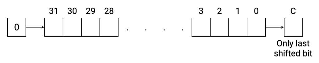
For left shifts, a zero is placed in bit 0 for each single bit shifted; the last bit shifted out of bit 31 is placed in PSR-C. For right shifts, a zero is placed in bit 31 for each single bit shifted; the last bit shifted out of bit 0 is placed in PSR-C.

There’s an additional shift op: Arithmetic Shift Right, ASRS. This is the same as LSRS except that instead of PSR-C being placed in bit 31, bit 31 remains unchanged. This is useful when you’re working with signed numbers because it allows you to retain the sign of the result.

There’s no ASLS because in operation it’s identical to LSLS.
Finally, we have Rotate Right, RORS, which rather than discarding the bit shifted out of bit 0 instead places it in bit 31 after the shift. This continues for however many individual bit-shifts you specify: set in the lowest byte of another register (there is no version with an immediate value as an operand).

Next time: all the remaining ops…
