
I haven’t been using a Picoprobe for a while because I needed to rebuild mine and issues with the code’s dependencies and a lack of updates from the Raspberry Pi Foundation meant I haven’t been able to get it to work properly. But I did spot this doohickey: a PCB you can solder a Pico and a header. It’s a much neater way to assemble a Picoprobe than breadboard and jumper wires.
And, at £9, it’s not expensive. But it is flawed, so I suggest caution before rushing to buy one.
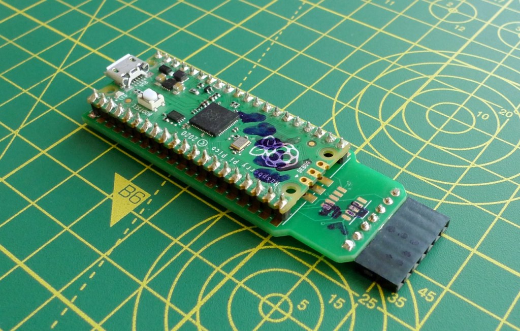
The PCB, as you can, takes a Pico. You can solder it directly to the PCB — I did this — or fit suitable header and then just clip the Pico on. The PCB comes with sets of male and female header for the business end: the feed from the GPIO pins through which the Pico — running the Picoprobe software — operates as a USB-to-SWD bridge.
In addition, the PCB ships with a JTAG header and cable, a connector more familiar to embedded engineers.

The Pico’s GPIOs 2, 3 are routed to the SWD IO and CLK output, as is a GND pin — you connect these pins to the SDWIO, SWDCLK and GND pins on your test Pico at the opposite end to the USB port.
GPIO 4 and 5 are routed to the PCB header’s SWO and RESET pins — despite the name these are the Picoprobe’s stdio UART pins.

What the PCB doesn’t have — and this, for me, is the killer — is 3V3 output. There’s a header marked VREF — you can see it in the pics above — but it’s connected to GPIO 28. Did the designer mean to connect the header pin to the Pico’s ADC-VREF pin, which is the next one along? Possibly, but it’s still not a 3V3 output that you can use to power the test Pico. That’s the next one along.
So you can’t power your test Pico from a PCB-mounted Pico, at least not without adding extra wiring, and that kind of defeats the product’s purpose.
Nice idea — shame about the beta-release implementation. I say wait for version 2.0.
The Picoprobe PCB Kit is available from Pirmoroni and other Pico-friendly retailers.

If you need an image to update your picoprobe, you could pick one here: https://github.com/rgrr/yapicoprobe/releases. The custom picoprobe protocol is no longer supported, instead it does CMSIS-DAPv1 and v2. Additionally you can flash the target Pico via MSC.
Concerning your VRef issue: cut the connection with a knife (no problem cause it is a two layer PCB) and re-wire the connection at your will. That’s what we had to do in former days with every PCB because they all had bugs.