
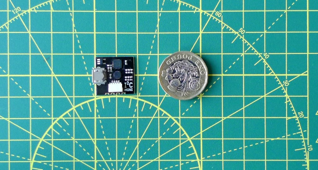
I’ve been messing around with the I²C Mini from Excamera Labs for a week or so. It’s a tiny, 19x19mm I²C breakout designed to to let you connect a wide array of components — displays, sensors, controls and such — to your computer.
You’d not use it with a machine like a Raspberry Pi, which has its own I²C pins exposed through the GPIO, but you can use it with a Mac, a Linux box or a Windows PC. You connect the I²C Mini to a spare USB port — it has a micro USB jack — and install a drive which communicates through a serial-over-USB link.
Excamera provides a Python driver, so it’s really easy to talk to the I²C Mini through Python code, and there’s a command line utility you can build if you need to use other languages. Excamera also publishes the serial protocol its drivers use to talk to the I²C Mini’s microcontroller to trigger I²C operations and relay data over the serial link, so you can write your own code capable of communicating directly with the unit.
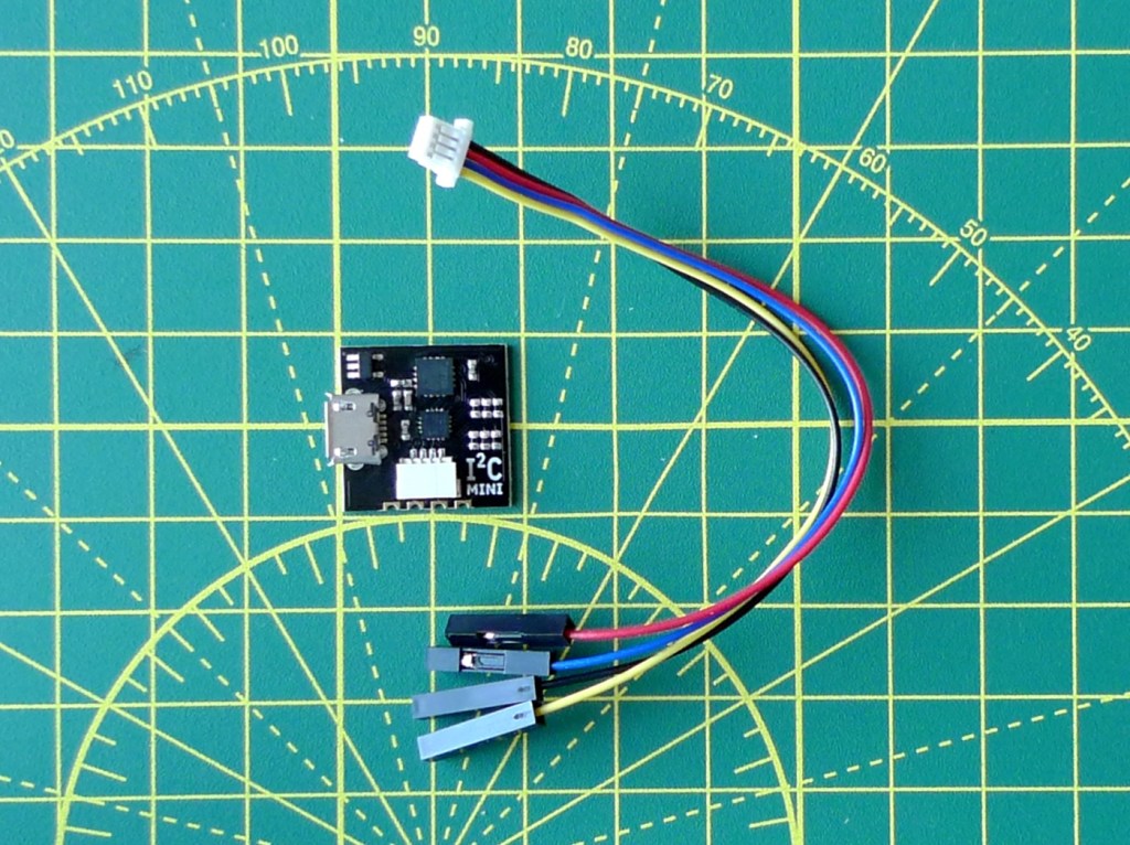
The breakout itself has four pins at the business end: GND, VCC, SDA and SCL. Power is rated at 3.3V, but are 5V tolerant. These pins are connected to a half-header on the board edge for surface-mount connections or to take four standard pins so you can clip the I²C Mini onto a breadboard. Those four lines are also wired to a four-pin 1.0mm pitch connector — the kind called Qwiic by Sparkfun and Stemma QT by Adafruit. The board comes with a 120mm cable that converts the Qwiic port to female header pins.
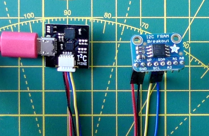
That pin count highlights the key gotcha with this board: if your I²C device requires additional pins, then the I²C Mini can’t help you. A case in point: I wanted to connect a 128×64 OLED panel to the board to try the system info display code I wrote to use with the MCP2221 GPIO breakout board. But the display has an extra pin that’s used to toggle chip resets, and there’s no way to drive it from the I²C Mini board. I came upon quite a few cases like this as I reached into my kitbox for I²C devices to try with the board.
However, if you‘re happy to be restricted to I²C devices that require only power, a ground connection and the two I²C lines, you’re good to go. The board has its own pull-up resistors, which can be enabled or disabled as required, so you can connect I²C devices direct to the breakout, though I used devices already mounted on their own boards with pull-ups already fitted.
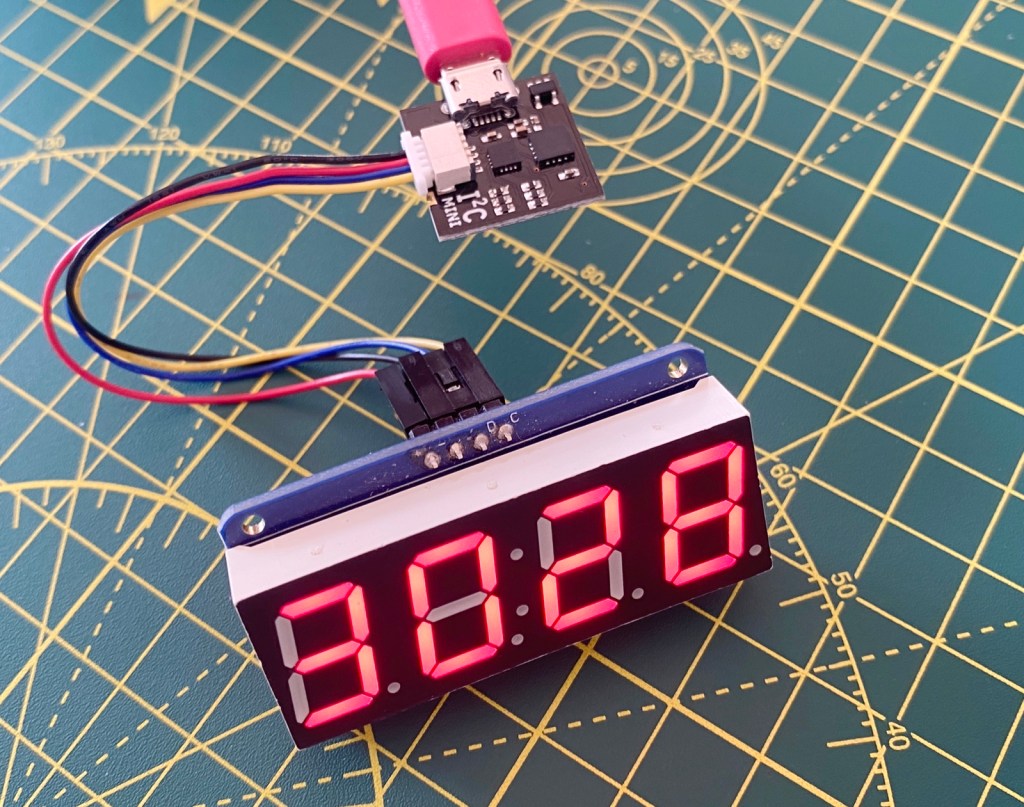
I tried the board with an MCP9808 temperature sensor and a Holtek HT16K33-driven four-digit, seven-segment LED display. The Excamera Python driver and command line utility both have a bus scan feature, so it’s easy to gather the I²C addresses of connected devices.
Under Python, you import the driver as a module and then instantiate an object based upon it. You provide the I²C Mini’s device path (Linux, macOS) or COM port (Windows):
i2c = i2cdriver.I2CDriver("/dev/cu.usbserial-DO029IEZ")
The simplest way to access connected devices is the driver instance’s regrd() function, which takes the target device’s I²C address, the address of the register or memory location you want to read from — I²C generally works by writing to or reading from specific registers in the peripheral device — and a string to indicate the format of the data returned by the call:
temp = i2c.regrd(self.addr, self.MCP_AMBIENT_TEMP_REG, ">H")
The formatting is required because the driver uses Python’s struct.unpack() function, so it’s a good idea to read up on that before proceeding. The example above, >H, returns the vale from the MCP9808 ambient temperature 16-bit register as an unsigned 16-bit integer (H) in big endian order (>).
You set the format for whatever data type your particular I²C device stores in the specified register, so keep its datasheet handy.
The regrd() function is useful because it handles all the I²C transaction management for you. The equivalent write function is regwr(). You can handle the transactions if you need to: there are start() and stop() functions to top and tail the transaction, and read() and write() to transmit and receive data.
The command line utility works in broadly the same way. The tool, i2ccl, takes the board’s device path or COM port, and a sequence of one or more commands. For example:
i2ccl /dev/cu.usbserial-DO029IEZ w 0x18 5 r 0x18 2
This line writes (w) to the device at address 0x18 the value 5 then reads (r) two bytes back from the same device.
The read operation auto-stops the I²C transaction; if you just write data, you need to stop the transaction manually, with the p command.
If you’re a Swift programmer, you can call i2ccl from a macOS app using Foundation’s Process class:
func getReading() -> Float? {
    var result: Float? = nil
    let task: Process = Process()
    task.executableURL = URL.init(fileURLWithPath: "/usr/local/bin/i2ccl")
    task.arguments = ["/dev/cu.usbserial-DO029IEZ", "w", "0x18", "5", "r", "0x18", "2"]

    do {
        try task.run()
        task.waitUntilExit()
        if task.terminationStatus == 0 {
            // CCL exited cleanly so process its output
            result = calculateResult()
        }
    } catch {
        // The CLI couldn't be run -- most likely it isn't installed
    }

    // Clean up and return
    return result
}
Check out my i2cdriver-mini repo for some sample code.
So the I²C Mini is a handy breakout if you’re building an add-on device that uses a set of simple I²C peripherals and is controlled by code running on the host computer. That might contain some simple sensors and basic display units, but you’ll be limited to devices that can operate with power and ground, and the two I²C lines. Any peripherals that need extra signalling will be a challenge to integrate. You’ll probably be better off with a board that offers I²C and GPIO, such as the MCP2221.
The I²C Mini costs around £16. I got mine from Pimoroni.
